An Intuitive Logical Formalism for the Description of Anatomical Movements We need a logical formalism for describing the anatomy of a structure in a way that leads naturally to the description of its movements. Quaternions and framed vectors provide an intuitive language for describing structure and movement. In order to see how they operate, it is necessary to examine a few attributes of quaternions. One might begin with a bit of history. Complex numbers were well known in the 1800’s and they were the focus of a great deal of the more advanced mathematics and physics of the time. An Irish mathematician, one of the great mathematicians of all time, Sir William Rowan Hamilton wondered if it might be possible to generalize the complex number, which are intrinsically two dimensional, to a form for three dimensions (Hamilton and Joly 1869; Joly 1905; Graves 1975; Stewart 2007). In particular, it was common practice to use complex numbers to represent rotations or periodic variations and he wondered if number like a complex number could represent rotations in three dimensions. It turns out that there are such numbers, but they are different in many ways, different enough that it took him about many years to see how to do it. Complex Numbers Consider complex numbers first. A complex number is the sum of a real number and an imaginary number. Real numbers are the number that we use every day to measure things. They are the decimal numbers. An imaginary number is a real number times the square root of -1, which is generally written as i. If ‘a’ and ‘b’ are real numbers, then the combination  is a complex number. is a complex number. Complex numbers may be interpreted as vectors in a plane. Two axes, the real number axis, which is usually horizontal, and the imaginary number axis, which is perpendicular to the real number axis, define the plane. 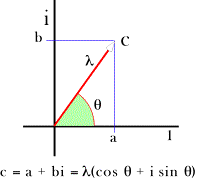
Note that one might also represent the complex number as a radius of a circle centered upon the origin. If the magnitude of the complex number is the length of the vector used to represent it,  , then its magnitude is the square root of the sum of the squares of its components. , then its magnitude is the square root of the sum of the squares of its components. 
The direction of the vector is  , the angle between the positive real axis and the vector. It follows that the complex number can be represented by the expression -. , the angle between the positive real axis and the vector. It follows that the complex number can be represented by the expression -. 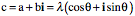
Addition of complex numbers is like the addition of vectors, in that one adds the real terms together and adds the imaginary numbers together and the sum of those two sums is the complex number that is the sum of the component complex numbers. 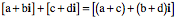
The elegance of complex numbers lies in the manner in which they multiply. Multiplication is basically algebraic, remembering that  . However, in the trigonometric notation, that works out to mean that the product of two complex numbers has a length that is the product of their individual lengths and an angle that is the sum of their angles. If one of the complex numbers has a length of 1.0, then it effectively rotates the other complex number through an angular excursion equal to its angle. . However, in the trigonometric notation, that works out to mean that the product of two complex numbers has a length that is the product of their individual lengths and an angle that is the sum of their angles. If one of the complex numbers has a length of 1.0, then it effectively rotates the other complex number through an angular excursion equal to its angle. 
The upshot of these properties of complex numbers is that a unitary complex number, one with a magnitude of 1.0, acts as a rotation operator for transforming other complex numbers by rotating them about the origin. That property is used extensively in physics, where the operator is often expressed in exponential form. 
These points are developed in more detail elsewhere (Langer 2005b; Langer 2005c; Langer 2005e) and in many standard mathematics texts. Quaternions [A summary of the formal structure of quaternions and the operations that may be performed with them is given in a later chapter. There are a number of other introductions to the formalism of quaternion analysis. (Hamilton and Joly 1869; Hardy 1881; Tait 1886; Joly 1905; Langer 2005b; Langer 2005c; Langer 2005d; Langer 2005e; Langer 2005f). In this chapter they will be introduced in a more heuristic fashion.] One might reasonably assume that if two components suffice to express rotations in two dimensions, then it would take three to express rotations in three dimensions. In fact, it takes four. In addition, there are some other peculiarities of three-dimensional rotations that lead to unexpected attributes for the formal system that describes them. Hamilton found that it took a real number and three different imaginary numbers (i, j, k) to characterize rotations in three dimensions. 
If we express the quaternion as a vector, then the i, j, and k unit vectors are directed in three mutually orthogonal directions and the vector of the quaternion is the sum of the last three components. The first component is a scalar. The coefficients (a, b, c, d) are all real numbers. The magnitude of the quaternion is the square root of the sum of the squares of its four components. The magnitude of the vector of the quaternion is the square root of the sum of the squares of the vector components. The magnitude of a quaternion is called its tensor, T. 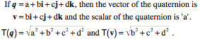
We can rewrite the expression for the quaternion as its magnitude times a trigonometric expression that contains a unit vector in the direction of the vector of the quaternion. 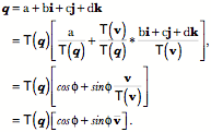
The angle, , is the angle of the quaternion and is the unit quaternion in the direction of the vector of the quaternion. It turns out that if one has two vectors, a and b, then it makes sense to consider the ratio of b to a to be a quaternion R such that the unit vector of R is the axis of rotation that turns a into b, f is the angular excursion of that rotation, and T is the ratio of the length of b to the length of a. To see how that is possible, one must examine the rules for addition and multiplication of quaternions. Quaternions add much as complex numbers did. Individual components add. 
Quaternions multiply algebraically with the following rules. 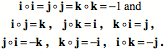
There are several observations that one might make here. All the vector components are imaginary numbers, because their square is -1. However, they are different imaginary numbers because the product of two different components is the third component or its negative. The order of multiplication is relevant. When the product is cyclic in the direction  , then the product is positive, when it is in the opposite direction, then it is negative. These rules can be applied to the multiplication of two quaternions as follows. , then the product is positive, when it is in the opposite direction, then it is negative. These rules can be applied to the multiplication of two quaternions as follows. 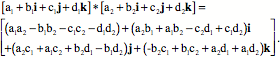
The actual multiplication of quaternions is tedious because one must be careful to maintain the order of the imaginary components, which takes a great deal of care. However, it is easy to train computers to carry out the operation, so in practice one usually delegates the multiplication to a machine, except in simple cases. Much the same applies to the multiplication of matrices, which also require one to be very careful of details. A few simple cases will be done below to illustrate the principles. However, the power of this approach becomes evident when one is dealing with the more complex situations where machine multiplication is almost essential. There is one other concept that needs to be introduced before we return to the consideration of anatomical rotations. In quaternion analysis it makes sense to take the ratio of vectors and it makes sense to have an inverse of a vector. In fact every quaternion has a unique inverse. The inverse will not be derived here, but it is relatively easy to see that the inverse is indeed an inverse. If a quaternion is written in trigonometric form then its inverse can be immediately written down as well. 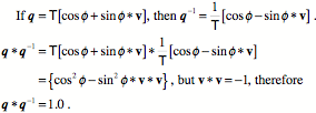
One can verify that the square of a vector is -1 by substituting the appropriate values in the formula for quaternion multiplication given above. In most of the situations that arise in anatomical movements, the rotation quaternion is a unit quaternion and the T term is 1.0, so the inverse of a quaternion is obtained by simply writing the quaternion with the vector of the inverse equal to the negative of the vector of the quaternion. Quaternion Rotations Let us consider a simple problem in which it is possible to begin applying quaternions to model rotations. First, assume that we have a vector that is aligned with the i axis, and we wish to turn it through 90° about the k axis. Since the axis of rotation is perpendicular to the vector that is being rotated, it is possible to use the definition of a quaternion to write the expression for the rotation. 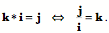
The first expression follows directly from the rules for the multiplication of the imaginary components. However, we can confirm its truth by starting with the observation that the ratio of j to i is , therefore, if we multiply both sides by i we get the first expression. Note that one must be careful to multiply in the same order on both sides. , therefore, if we multiply both sides by i we get the first expression. Note that one must be careful to multiply in the same order on both sides. 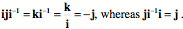
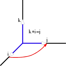
The quaternion k is the ratio of the vector j to the vector i. In quaternion analysis vectors are a special case of quaternions, that is, quaternions for which the scalar is 0.0. From this figure it is also obvious that i is the ratio of k to j and j is the ratio of i to k. The ratio of two orthogonal vectors is always a vector, because cos p/2 =0.0. Conversely, any vector can be expressed as a ratio of two orthogonal vectors. One can use simple multiplication by a quaternion to model a rotation only when the vector that is being rotated is perpendicular to the axis of rotation, as was the case here. Otherwise, it is necessary to use the slightly more complex, but more general, rule when computing a rotation ( ). In this instance, the angular excursion is 90° and the axis of rotation is the positive k axis, therefore the rotation quaternion (r) has an angle of 45°, which is half of 90°. Using the general formula for rotations, the product is as follows. ). In this instance, the angular excursion is 90° and the axis of rotation is the positive k axis, therefore the rotation quaternion (r) has an angle of 45°, which is half of 90°. Using the general formula for rotations, the product is as follows. 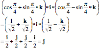
This second calculation was needlessly complex for this situation, but if the situation were different, then it would be essential to use the second, more general, form of multiplication. To illustrate this point, let us consider an instance where the rotation causes the moving vector to sweep out a conical surface. Consider the rotation of the vector i+k rotated 90° about the k axis. The calculation is like the last one except for having i+k in the place of i. We know that the result should be j+k and that is what the calculation yields. 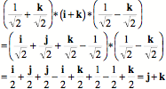
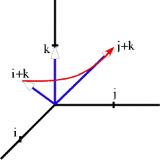
When the axis of rotation is not perpendicular to the rotating vector, then the more general formula for rotation is necessary. Such rotations are called conical rotations, because they sweep out a conical surface. Of course, these are very simple and straightforward calculations, chosen so that the correct vector is apparent from the pictures. The correct vector is much less apparent if the axis of rotation is at an odd inclination and the angular excursion is not a neat fraction of a circuit. In such circumstances, the resultant vector is slightly more difficult to calculate, but still readily calculated with the simple method illustrated here. Additional concepts involving quaternions will be introduced as we go along, but a great deal can be done with what has been introduced so far. Spin and Swing Spin and swing have been long-standing concept in kinesiology (White and Panjabi 1978; Nordin and Frankel 1989; White and Panjabi 1990; Bogduk and Twomey 1991; Williams, Bannister et al. 1995; Bogduk 1999). They are fairly intuitive in that spin is basically the rotation of an object about its axis and swing is a rotation of an object in which an axis of the object sweeps out an arc. Pure swing occurs when the arc is confined to a plane perpendicular to the axis of rotation. If one turns one’s head from looking straight ahead to looking over a shoulder, then one’s head experiences a spin about a vertical axis that runs between the occipital condyles. On the other hand, if one nods one’s head, then it swings about a horizontal axis through the occipital condyles. There is clearly a problem with these intuitive concepts. It is apparent in the manner in which the descriptions were given. Each involved a definite reference structure and an axis of rotation. If the nose had been chosen to be the reference in the first instance, then one would say that it swings about the vertical axis. The same movement is both a spin and a swing. Consequently, spin and swing are not descriptions of a movement, unless one knows the context in which it being viewed. These concepts imply a frame of reference, with a differential weighting of the axes of the frame such that one axis is taken a the principal feature of the object, and an axis of rotation that that feature moves about. In most situations where the terms are used, the frame of reference is not stated and often the axis of rotation is not explicitly stated either. Sometimes one can deduce the implied frame of reference from the context of the description, sometimes one cannot. If a lumbar vertebra swings to the left, what does that mean? One assumes that the anterior midline of the vertebra is the point of reference and that the axis of rotation lies in the mid-sagittal plane. However, the axis may be the superior/inferior axis or the anterior/posterior axis or an axis somewhere in between vertical and horizontal. It may pass through the vertebral body, through a facet joint or through a point that lies completely outside the vertebra. In each case the movement is quite different. Clearly, this situation is unsatisfactory, if one wishes to seriously discuss anatomical movement. And yet, spin and swing capture something that seems very intuitive. One might ask if there is a way to rescue the concepts while creating the precision that is necessary to accurately and clearly describe movements? Consider an example of an anatomical object that is rotating. A lumbar vertebra is chosen and a frame of reference, {r, s, t}, is attached so that the r axis is directed perpendicular to the anterior face of the vertebral body, the s vector points directly to the left and the t vector is perpendicular to the superior face of the vertebral body. Note that the attachment is not to any particular point in or on the vertebra, because orientation does not have location. Let the center of the vertebra lay midway between the superior and inferior surfaces of the vertebral body and midway between the anterior and posterior surfaces in the mid-sagittal plane. A lumbar vertebra has a body that is about 2.5 cm high, 3.0 cm deep, and 3.5 cm wide. A point on the superior surface might be expressed by the extension vector {r. s. t} = {0.0, 0.0, 1.25}. The center of the anterior face would be {1.5, 0.0, 0.0} and the left lateral margin would be {0.0,1.75, 0.0}. The usual description usually assumes that the point of reference is the anterior midline of the vertebral body. The frame of reference is usually assumed to be the one illustrated here. The axis of rotation is often unclear, but it is often implicitly assumed to be a vertical axis aligned with the longitudinal axis of the body. Let us consider a few possibilities. 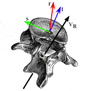
In this example the frame of reference is aligned with the anterior/posterior (r), medial/lateral (s), and superior/inferior (t) axes of the lumbar vertebra. The axis of rotation () is approximately the axis of lateral rotation for the vertebra. Rotation about an axis through the center of the vertebra If the axis of rotation runs through the center of the vertebral body and perpendicular to the superior and inferior surfaces of the vertebral body, then the rotation is expressed by the following quaternion. 
Let {r, s, t} = {i, j, k}, then the rotation of the three extension vectors can be written down by inspection. The calculation is written in terms of an array of extension vectors. 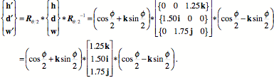
If the angular excursion is 45° to the left, then the calculation can be carried out and the new values for the height, depth, and width extension vectors written down. 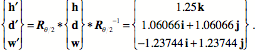
The height vector, h, is not changed by the rotation. That is because it experiences spin. Spin does not alter the direction of a spun vector. Since the extension vector for height is expressed in terms of that vector and only that vector, it is not altered. Both the depth vector, d, and the width vector, w, experience pure swing. They move in the plane perpendicular to the axis of rotation. By inspection one can see that the new values are the correct values for 45° rotation to the left about a vertical axis through the center of the vertebra. Rotation about an axis not through the center of the vertebra If the axis of rotation is not through the center of the vertebral body, but though the center of the spinal canal, then the change of orientation is the same. Consequently, the above calculations are still valid. However, since the location does depend on the position of the center of the vertebral body relative to the axis of rotation, we must perform an additional calculation. Let the axis of rotation be through a point in the center of the spinal canal {-2.0, 0.0, 0.0}, then the vector to the center of the vertebral body is {2.0, 0.0, 0.0}. The new location, in coordinates relative to the center of rotation, is given by the following expression. 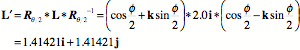
The new location of the center of the superior face of the vertebral body is the location of the vertebra plus the extension vector for the superior face, 1.414 i + 1.414 j + 1.25 k, and similarly for the other two points, (2.474871 i + 2.47487 j) and (0.17677 i + 2.65165 j), respectively. Rotation about an axis tilted relative to the frame of reference This situation can be generalized further by allowing the axis of rotation to be tilted relative to the frame of reference for the vertebra. First consider the situation where the axis of rotation is through the center of the vertebra. Let the axis of rotation be tilted 45° anterior when superior to the vertebral body. That makes the quaternion that expresses it a function of i and k. 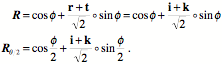
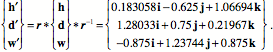
The new height, depth, and width vectors are computed much as before, but the calculations are somewhat more complex because of the tilted axis of rotation. 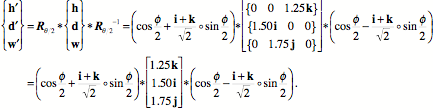
You can check that these are still orthogonal vectors by taking the ratio of any two in the appropriate sequence. The unit vector of the ratio is the unit vector of the third extension vector. It is easier to see what is occurring if we examine the transform of the frame of reference, because of the symmetry of the vectors. 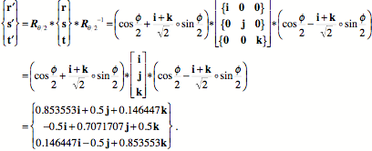
It is straightforward to check that the three transformed unit vectors are still orthogonal, by taking the ratio of each pair and getting the third vector. It is also easy to show that the ratio of the transformed r and t vectors to the original vectors has an angle that is not 45° or 0°, therefore neither transformed vector is perpendicular to or parallel with the original vector. Consequently, neither experienced a spin or a pure swing. The angle of the ratio of the transformed s vector to its original value is 45°, therefore it experienced a pure swing. That is what one would expect from the geometry of the situation. Now consider the situation when the axis of rotation is tilted posterior when superior to the vertebral body. The equations can be written with minor changes from the set that have just been considered. 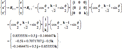
Much the same remarks can be made about this transformed frame of reference as was noted for the anteriorly tilted axis of rotation. The principle differences are a change in the sign of some of the coefficients. Of course, the transformed orientations are quite different from each other. Fryette’s Laws or Principles In 1918, a chiropractor named Harrison H. Fryette formulated two principles related to physiological spinal movement, which were extended in 1948 by another chiropractor, named C.R. Nelson, so there are three laws or principles. They are as follows. I. When the thoracic and lumbar spine is in a neutral position (easy normal), the coupled motions of sidebending and rotation for a group of vertebrae are such that sidebending and rotation occur in opposite directions (with rotation occurring toward the convexity). II. When the thoracic and lumbar spine is sufficiently forward or backward bent (non-neutral), the coupled motions of sidebending and rotation in a single vertebral unit occur in the same direction. III. Initiating motion of a vertebral segment in any plane of motion will modify the movement of that segment in other planes of motion. The calculations that we have just performed have a bearing upon these observations. The observations relate to a view of the spine and its movements that divides all movements up into cardinal movements in three orthogonal planes. Rotations in a sagittal plane are flexion, if you bend forward, and extension, if you bend backwards. Rotations in the coronal plane are sidebending or side flexion to the right or the left, where the direction is named for the direction that the superior aspect of the vertebra moves relative to the inferior aspect. Rotation in a horizontal plane are simply called rotation to the right or left, where the direction is named for the direction that the anterior aspect of the vertebra moves relative to the posterior aspect. According to this way of classifying movements the excursions that our lumbar vertebra experienced was not a single circular movement about an axis of rotation, but a combination of a sidebending and a rotation, that is, two coupled movements about two mutually orthogonal axes. Leaving aside the needless and misleading obfuscation introduced by this approach, let us consider the computed movements from the point of view of cardinal planes of rotation. Viewed face-on, from directly in front of the vertebra, the transformation of the vertebra that rotated about an anteriorly tilted axis, appears to be a rotation to the left and a side-flexion to the right. The vertebra that rotated about a posteriorly tilted axis, appears to rotate to the left and side-flex to the left as well. Clearly, the designation of right and left is completely arbitrary for both sidebending and rotation, so whether both move in the same direction is arbitrary. However, much is made of this apparent coupling of lateral rotation and side-flexion. These are the relationships encoded in Fryette’s laws. The association has been ascribed to properties of the vertebra, but one can see from the calculations that were just performed that it is a property of any rotations in three-dimensional space. To the extent that the coupling is due to the vertebra, the constraints on rotation imposed by the facet joints are important to determining the axis of rotation. However, Fryette’s laws do not relate to the axis of rotation of the vertebra, but to the consequences of side-flexion of the lumbar spine as a whole. Basically, Fryette’s laws say that if the spine is at rest, then the axes of rotation for the spine are tilted anteriorly relative to the frame of reference for the vertebrae. If the spine is taken into an endrange configuration, then the axes of rotation are shifted to tilt posteriorly relative to the orientations of the vertebrae. The third law is due to the restraints imposed upon the spine by the ligaments and facet joints of the vertebrae so that as a vertebra approaches one of the restraints upon its movement, it reduces the extent to which it can move. That is hardly a startling observation. It would be much more impressive if the nature of the restraint predicted the nature of the limitation. In fact it does, but the third law says nothing about such things. The interesting aspect of Fryette’s laws are not what they say about movements, but what they imply about the determination of the axes of rotation in the spine. Consider a lumbar vertebra such as illustrated above. The axis for sidebending is between the inferior facet joints, approximately in the midline, if the vertebra is approximately in neutral position. As one facet slides down the other slides up (0° axis). If the vertebra is in a situation where the back is in endrange of flexion or extension, then in order to sideflex, one facet must slide down or up while the other acts as a fulcrum for the movement. There is no other way to move. In both situations, the inferior margin of the spine is another fulcrum, either because of abutment with the subjacent spine (maximal extension) or because it is at the end of a maximally stretched interspinous ligament (maximal flexion). As indicated upon the figure that means that the axis of rotation is elevated approximately 30° (maximally flexed) or depressed 30° (maximally extended). We can see from the next figure that the axis of rotation is approximately 30° laterally directed as well. 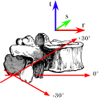
The axes of sideflexion rotation for full extension and full flexion are tilted about 30° relative to the approximate axis for sideflexion in neutral position. The two points that are thought to determine the axis of rotation in endrange positions are the inferior margin of the spine and the upper and a lower limits of the facet joint. The axes are also tilted about 30° laterally (see below). 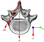
The abutment or tethering of the vertebral spine and the facet joint force the axis of rotation to be through the points of restriction. For a lumbar vertebra, that means that the axis shifts from the midline to an axis directed about 30° lateral to the midline and tilted up or down about 30° (see previous illustration). Given these observations, we can write out axes of rotation for the sidebending movements. For neutral position, the axis is simply parallel with the r axis. If we let the r axis of the frame of reference be in the direction of the i component of the universal coordinates then we can write the expression for the neutral rotation quaternion. 
Similarly, we can write the rotation quaternions for the endrange movements. 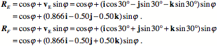
For each axis of rotation we can compute the transformation of the vertebra’s orientation frame, f, as was done above. 
With 45° of rotation the new frames of reference are as follows. 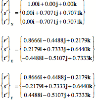
For neutral position the sideflexion has no rotation component, however, if the axis of rotation is tilted inferiorly, then there will be a concurrent rotation in the same direction and if it is tilted up there will be a rotation in the opposite direction. According to Fryette’s laws, this would mean that the axis of sideflexion in neutral position is usually tilted so that its anterior end is superior to its posterior end. Given the anterior lumbar convexity, it might generally be the case that the axis of sideflexion lies in such a relationship, superiorly tilted, to the lumbar vertebrae being examined. In endrange extension, the vertebra moves into right sideflexion and right rotation. In endrange flexion, the vertebra moves into left sideflexion and right rotation. The inclination of the axis of rotation has opposite consequences in the two situations. Of course the magnitude of the rotations are not 45°. Most measurements would place them at less than 10° in adults. If such a rotation occurs then the magnitudes of the concurrent movements are substantially less. Using 10° of sideflexion in the endrange situations, where the effect is largest gives a transformed orientation like the following. 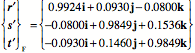
Given the dimensions of a lumbar vertebra, on the order of one or two centimeters, the concurrent movements are on the order of one or two millimeters. Given that the palpable part of the vertebra is the vertebral spine, which lies nearly on the axis of rotation for sideflexion in endrange positions, the movements would be much smaller. There must be some skepticism about whether such concurrent movements can be palpated on the individual vertebral level. Bogduk, N. (1999). "The neck." Baillieres Best Pract Res Clin Rheumatol 13(2): 261-285. Bogduk, N. and L. T. Twomey (1991). Clinical Anatomy of the Lumbar Spine. New York, Churchill Livingstone. Graves, R. P. (1975). Life of Sir William Rowan Hamilton. New York, Arno Press. Hamilton, W. R. and C. J. Joly (1869). Elements of quaternions. New York,, Chelsea Pub. Co. Hardy, A. S. (1881). Elements of quaternions. Boston,, Ginn Heath & co. Joly, C. J. (1905). A Manual of Quaternions. London, Macmillan and Co. Ltd. Kuipers, J. B. (1999). Quaternions and Rotation Sequences: A Primer with Applications. Princeton, New Jersey, Princeton University Press. Langer, T. P. (2005b). Modeling Rotations of Orientable Objects in Three Dimensions: An Introduction to Quaternions and Framed Vectors.: http://homepage.mac.com/tlanger_sasktel_net/Theory/quaternions.html. Langer, T. P. (2005c). Geometrical Anatomy and Anatomical Movements: An Introduction to the Use of Quaternions and Framed Vectors in the Description of Anatomical Rotations. : http://homepage.mac.com/tlanger_sasktel_net/Theory/quaternions.html. Langer, T. P. (2005d). Commentary on Joly’s Manual of Quaternions: http://homepage.mac.com/tlanger_sasktel_net/Theory/quaternions.html. Langer, T. P. (2005e). Structural Ratios: The Comparison of Structures and Their Parts.: http://homepage.mac.com/tlanger_sasktel_net/Theory/quaternions.html. Langer, T. P. (2005f). The Geometrical Anatomy of Compound Movements.: http://homepage.mac.com/tlanger_sasktel_net/Theory/quaternions.html. Nordin, M. and V. H. Frankel (1989). Basic Biomechanics of the Musculoskeletal System. Philadelphia, Lea & Febiger. Stewart, I. (2007). Why Beauty is Truth. A History of Symmetry. New York, Basic Books. Tait, P. G. (1886). "Quaternions:" Encyclopedia Britannica, 9th Edition. Weisstein, E. W. (1999). "Quaternions." From MathWorld--A Wolfram Web Resource. White, A. A. and M. M. Panjabi (1978). Clinical Biomechanics of the Spine. Philadelphia, J. B. Lippincott. White, A. A. and M. M. Panjabi (1990). Clinical Biomechanics of the Spine. Philadelphia, J.B. Lippincott. Williams, P. L., L. H. Bannister, et al. (1995). Gray's Anatomy. The Anatomical Basis of Medicine and Surgery. New York, Churchill Livingstone. |