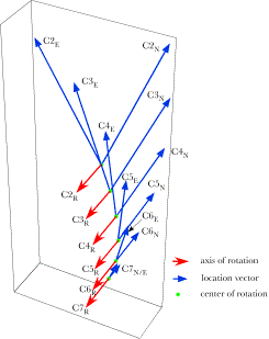
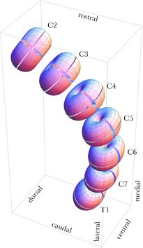
Spinal Dynamics IV: Applying the Model to the Lower Cervical Spine Applying the Models to the Lower Cervical Spine to Analyze Its Movements The tools developed in the last chapter can be used to examine a wide variety of problems related to the description of movements in the lower cervical spine. In this chapter we will consider a few examples. The first examples will be fairly simple and direct, examinations of the manner in which the spine moves when the movements are of one type, such as extension in each and every intervertebral joint. Then, we can make it little more difficult by examining movements that combine both sagittal and oblique movements from neutral configuration. The next step is to consider movements between eccentric configurations and the effect of varying the magnitude of the angular excursions. Finally, we will touch on the consequence of examining movements by breaking them into a great many small segments and describing the movements in terms of a stream of centers and axes of rotation. The distribution of the centers of rotation for extension of the lower cervical spineTo return to the description of the movements in the lower cervical spine during extension, if we assume the spine starts in neutral configuration, that the distribution of extension between the joints is as given above, and that the point of reference is the location of the T1 vertebra, then it is possible to compute the centers of rotation for the individual vertebrae. We would expect the centers to lie in the midsagittal plane, since all the movements occur in that plane. We would expect the centers to reflect the fact that the more rostral vertebrae move further and through a greater angle of excursion. In addition, we would expect the arcs to be nearly circular, but should not be surprised if they turn out to be somewhat distorted. If we compute the centers of rotation for each of the cervical vertebrae moving from neutral configuration to full extension, taking the center of T1 as the reference point, then the distribution is as illustrated in the following figure. Amounts of extension in the intervertebral joints is assumed to be 5°, 7.5°, 10°, 10°, 7.5°, and 5° in successively more caudal joints. The blue vectors indicate the locations of the cervical vertebrae in neutral position, prior to the extension ( All the rotations occur in the midsagittal plane so all the axes of rotation point directly lateral. It is striking how different the experiences of the most rostral and the most caudal vertebrae are. The C7 vertebra rocks slightly upon T1 and the center of rotation is near or in the intervertebral disc. C2 has a large excursion (45°) that takes it dorsally and slightly posteriorly in the midsagittal plane. Its center of rotation is at a rostro-caudal level between C4 and C5 and dorsally displaced. The movements of most of the vertebrae are effectively at the level of more caudal vertebrae. Consequently, watching the lower cervical spine extend, one would have the impression that all the movement is occurring in the lower neck. We will find that such an illusion is a common feature of all movements in the neck. Sagittal movements are particularly apt to have markedly caudally displaced centers of rotation.
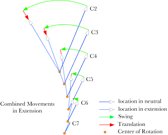
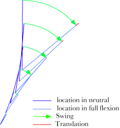
Extension in the lower cervical spine. The changes in location due to extension are indicated by the blue vectors, which point to the initial and final positions of the vertebrae relative to the centre of rotation for each vertebra. The axis of rotation is indicated by the red vectors that extend perpendicular to the midsagittal plane. The centers of rotation lie within the midsagittal plane along a curvilinear line that is concave dorsally. It is difficult to assess in the above figure, but the arcs that the vertebrae sweep out are not circular. If we replot the data to look from the side, then the relative amounts of swing and translation are more readily appreciated. In the following figure the vector from the center of rotation to the initial location of the vertebra is drawn then a circular arc is swept out to bring the vector into alignment with the final position. When that is done here, the final terminus is not at the location of the vertebra at the end of the movement. To bring it to the final position, it is necessary to translate the vertebra towards the center of rotation, by a distance indicated by the red arrows or lines. In general the magnitudes of the translations are small compared with the length of the swinging vector. However, the relative sizes of the translations grow with more progressive vertebrae. If there were another vertebra in the chain, then the translation would become appreciable. It is common to find that the movements of C2 and C3 have nonlinearities that begin to distort the character of the movements. The movements of the neck would probably be appreciably different if there were several more vertebrae, as in birds. The other way in which one can obtain greater consistency in the movements of the vertebrae would be to make the component movements smaller.
The relative amounts of swing and translation in the extension movements of the lower cervical spine are plotted in the midsagittal plane. The green arcs indicate the part of the trajectory due to the swing required to account for the change in orientation and the red segments are the translations necessary to move the vertebra to its final location. For the most caudal vertebrae the movement is nearly completely swing (green vectors), but, for the more rostral vertebrae, there begins to be a substantial amount of translation as well (red vectors). Since the model is quantitative, one can readily obtain values for all the parameters illustrated in the figure. Of particular interest here is the amount of translation. The translation vectors for the cervical vertebrae are given in the following table. The units are normalized to the height of the vertebral body, which is set equal to 1.0.
Translations for Cervical Vertebrae Moving into Full Extension
As indicated in the diagram, the amounts of translation in the caudal part of the lower cervical vertebrae are minimal. C4 is carried caudally about a fifth of a vertebra; C3 travels about 4/10ths and C2 moves about 2/3rds of a vertebral height. C2 is also carried ventrally a short distance. In all instances, the amount of translation is small compared with the amount of swing that a vertebra experiences. For pure extension, the dominant component of the movements is swing in the midsagittal plane. However, the more rostral the vertebra, the greater the translation component, both absolutely and relatively. The distribution of the centers of rotation for flexion of the lower cervical spineThe cervical spine is nearly symmetrical in its ranges of motion in flexion and extension. Therefore we can obtain a reasonable approximation of cervical flexion by substituting positive values for sagittal joint excursions in the model for the negative values associated with extension. The resulting plot is shown in the following figure.
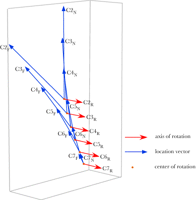
The lower cervical spine in full flexion. The viewpoint is from the ventral right side. Note that even in full flexion the facets in the zagapophyseal still overlap by a moderate amount. The spine achieves a slight flexion in the opposite direction, but is nearly straight at full flexion. The superior facet in each zagapophyseal joint has slid rostrally relative to the inferior facet The changes in the location vectors and the axes of rotation are illustrated in the following figure. The axes of rotation are in the opposite direction, therefore it was necessary to rotate the image through 180° in order to have them come out of the page, in the same manner as for the plots of extension. All the location vectors are in the mid-sagittal plane and all the rotation vectors extend directly laterally. As with extension, the centers of rotation are clustered in the inferior spine, just anterior to the center of the vertebral bodies. The center of rotation for C2 also lies only a short distance above the center of C5. The centers of rotation tend to lie in the ventral part of the vertebral bodies, near or ventral to the mid-coronal plane of the vertebral body. Once again, because of the caudal placement of the centers of rotation, the lower cervical spine appears to move primarily in the lower part of the neck when it moves into flexion.
Flexion occurs in each and every intervertebral joint of the lower cervical spine, to the extent that was used for the extension above. The conventions are the same as in the previous figure for extension. Flexion carries the vertebral body a short distance further ventral and rostral to the location that it would have if only swing occurred. That is, the translation is in the opposite sense from the translations in extension, which carried the vertebral body a short distance caudally and dorsally. The relative amounts of swing and translation are illustrated in the following figure, which has been rotated through 180° relative the above figure. The amounts of translation are so small that it is not possible to put arrowheads on the vectors, because the arrowhead would be longer that the shaft of the vector..
The numerical measures of translation are given in the following table. They are smaller than those for extension, but increase both absolutely and relatively for more rostral vertebrae.
Translations for Cervical Vertebrae Moving into Full Flexion
The distribution of the centers of rotation for oblique rotation of the lower cervical spineThe components of compound oblique movements in the lower cervical spine are somewhat more complex. However, this is where this type of analysis comes into its own, because the movements are no longer in cardinal planes and they are of sufficient complexity that the descriptions are not obvious. The movement of the neck is a twisting that does not greatly change the contour of the neck, but it does pull the C2 vertebra to the side, tilts it laterally, and rotates it laterally. The illustrated example in the following figure shows a neck that is right rotated and right sideflexed by negative oblique rotations about the oblique axes of the vertebrae. The magnitude of the excursions in each joint is the same as was used for extension and flexion in the previous examples. Indications are that the angular excursion about the oblique axis is comparable to that about a transverse axis for these joints. The final configuration of the spine is a reasonable approximation to the configurations described elsewhere for this movement (Kapandji 1974).
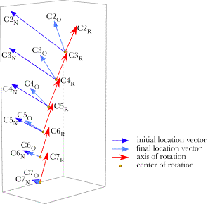
An artificial lower cervical spine that has been rotated in the negative direction about the oblique axis in each joint. The individual vertebrae are tilted to the right and laterally rotated to the right. The following calculations of the axes of rotation are based on a positively rotated spine, which twists the vertebrae to the left. Negative oblique rotation gives a more satisfactory image, but positive rotation give more readily appreciated plots of the movements. The most obvious difference from the movements in the sagittal plane is the tilting of the axes of rotation in a direction that comes closer to lying in a sagittal plane. The axes are tilted dorsally at approximately 45°, which would be approximately perpendicular to the plane of the facet joints. It is more difficult to appreciate but the centers of rotation do not lie in a single plane. As one progresses rostrally, the centers of rotation shift laterally.
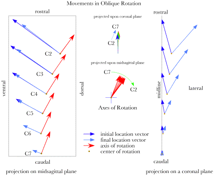
The centers of rotation and axes of rotation are plotted for oblique movements in the lower cervical spine. The dark blue arrows indicate the locations of the vertebrae in neutral position relative to the centers of rotation. The light blue vectors are foreshortened because they have rotated towards the viewer, that is out of the page. While the axes of rotation are tilted primarily posteriorly from a vertical direction, they are also slightly laterally tilted, towards the opposite side. The centers of rotation do not lie in the midsagittal plane, except for C7. The framework of location vectors and axes of rotation are shown for positive rotation about the oblique axes for each vertebra. The centers of rotation appear to lie in or near a single sagittal plane, but calculations and projection upon the cardinal planes show that they shift laterally for more rostral vertebrae (right panel of following figure). The lateral shift is much less than the lateral excursion of the vertebra, so, the vertebrae become more laterally tilted as one progresses rostrally. The axes of rotation are plotted with a common origin in the two central panels. The upper panel is for the axes of rotation projected upon a coronal plane and the middle panel is for the same vectors projected upon a sagittal plane. The axes are nearly vertical in the projection upon a coronal plane, but there is a small progression to left for more rostral vertebrae (upper central panel). When projected on a sagittal plane the axes of rotation tilt progressively more dorsally as one progresses rostrally (middle central panel). The centers of rotation shift posteriorly and laterally for progressively more rostral vertebrae (left panel in the following figure). It is noteworthy that the centers of rotation sit caudal to the centers of the vertebrae at each level and the caudal shift is progressively greater with more rostral vertebrae, but the extreme caudal shifts of the centers or rotation that occurred with extension and flexion do not occur with oblique rotations. The axis of rotation vector is always a unit vector, therefore it makes a convenient index of distances in these figures. A vertebra is about 0.8 units tall and a vertebra plus an intervertebral disc is about 1.2 units tall. Where the center of rotation is most caudally shifted, C2, it is bit more than one vertebral segment caudal. The centers of rotation are substantially less caudal than those for extension and flexion.
The projections upon the sagittal plane also show that the initial location and the final locations are almost in the same oblique plane for most vertebrae. The more rostral vertebrae experience a small rostral shift with oblique rotation. Because the dynamics of oblique rotations are more complex than those for sagittal movements, it is more useful to examine the numerical descriptions of the centers of rotation and the amounts of translation and swing. The translations are in all three dimensions, but significant only for lateral displacement of the more rostral vertebrae. The translation is towards the opposite side from the displacement of the centers of rotation, so that it largely compensates for the displacement of the center of rotation at each level.
Translations for Cervical Vertebrae Moving Obliquely
Centers of Rotation for Cervical Vertebrae Moving Obliquely
The centers of rotation for the progressively more rostral vertebrae shift dorsally and laterally until the C2 vertebra is rotating about a center that is about four-tenths of a unit lateral to the midline. Most of the centers of rotation are centered over the center of the T1 vertebra, so the movement appears to be essentially a twisting about a vertical axis that passes through the base of support for the neck. The rotation quaternions are listed in the following table and they are translated into swing in the final table. In both tables, it is clear that the axes of rotation are predominantly in the rostro-caudal axis with a moderate amount of tilting into extension, that is, dorsally. There is very little sideways tilt and that is to the side opposite the direction of movement. The angular excursions are slightly less then the sum of the excursions in the joints caudal to the vertebra, but, at most only a fraction of a degree. Of course, the excursion in the most caudal joint is the value that was set for that joint. The close agreement with the sum of movements in the subjacent joints may seem obvious, but that is not necessarily the case. When we mix sagittal and oblique movements, the angular excursions of the concatenated movements may deviate substantially from the sum of the subjacent joints’ movements.
Rotation Quaternions for Cervical Vertebrae Moving Obliquely
Swing for Cervical Vertebrae Moving Obliquely
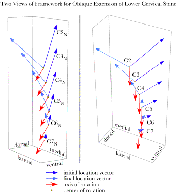
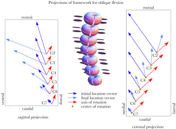
The distribution of the centers of rotation for sagittal and oblique rotation of the lower cervical spineThe cervical spine is capable of mixing oblique and sagittal movements to varying degrees to obtain a wide spectrum of configurations. At this point, we will examine only a couple of instances. Later we will explore these more complex configurations and the movements that lead to them in considerably more detail. The first example is a spine that is both extended and obliquely rotated to the right. Both the sagittal and the oblique movements are in negative directions. An image of that artificial spine is shown in the following figure. The values chosen for both movements were the values used in the previous examples, with maximal intervertebral excursions (10°) to either side C5 and progressively less in the more distant joints (7.5° and 5°). The C2 vertebra is laterally displaced to the right, tilted to the right and dorsally, and rotated to the right.
The artificial lower cervical spine has experienced equal negative rotation about the transverse and oblique axes in each intervertebral joint. The angular excursions in the joints are as in the previous examples for extension and oblique rotation. The shifts in location for all the lower cervical vertebrae and their axes and centers of rotation are illustrated in the following figure. Two viewpoints are given to give a better impression of the movements. The angular excursions are substantial, as one might expect. C2 experiences a 63° swing. The rotations carry the vertebrae laterally and dorsally. Like the previous examples, the movements in C7 are small while those in C2 are large. The axes of rotation are directed caudally and laterally to the left side, in much the same direction for all the vertebrae. The centers of rotation for the upper vertebrae lie at some distance dorsal to the vertebral bodies in their neutral positions.
Framework for the lower cervical spine with equal parts extension and oblique rotation to the right. Two views are given to assist with understanding of the spatial arrangement of the vectors. When the framework is projected upon coronal and sagittal planes it is easier to appreciate the relationships between the elements. In the coronal projection, we can see that the centers of rotation lie to the left side of the vertebral bodies in neutral configuration, in the opposite direction from the direction of turning. In the panel showing the projections upon a sagittal plane, the centers of rotation are obviously displaced caudally and dorsally. For the more rostral vertebrae the centers are a considerable distance from the locations of the vertebrae. The lengths of the armatures are intermediate between those for pure oblique rotation and those for pure sagittal movements.
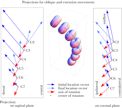
The framework for oblique extension of the lower cervical spine is projected upon a sagittal plane (left panel) and a coronal plane (right panel). The midsagittal plane is indicated in the right panel to emphasize the displacement of the centers of rotation in the direction opposite the direction of rotation. As the situation becomes more complex, it becomes more useful to examine the numerical values of the pertinent variables. We will now turn to the same four tables as were given above for oblique rotation. The translation components are lateral and caudal with very little dorsal/ventral shift. That is they occur in a nearly coronal plane. If the neck rotates to the right, then the translations are to the left, that is, contralaterally. All the centers of rotation are also shifted to the side contralateral to the direction of oblique rotation. The two offsets are of comparable size and additive. Comparison with the locations of the vertebral bodies indicates a substantial caudal placement of the centers of rotation. The C2 vertebra sits at 6.34 units rostral to the center of T1 when the spine is in neutral configuration and its center of rotation in combined oblique rotation and extension is at 4.01 units, about the level of C4.
Translations for Cervical Vertebrae Moving Obliquely into Extension
Centers of Rotation for Cervical Vertebrae Moving Obliquely into Extension
The axes of rotation are tilted ventrally and caudally and towards the opposite side, with the medial/lateral component being consistently greater than the other two. While there is variation between the levels of the spine, all the axes of rotation are in the same general direction. The rotation of the directions of the axes is mainly in the sagittal plane. If we add the angular excursions in all the joints, there would be 45° of extension and 45° of oblique rotation. When the two are combined, the amount of swing for C2 is 63.22°. Such nonlinear addition of rotations is usual in such systems, where rotations about different axes combine. The magnitude of the discrepancy between the sum of the angular excursions and the excursion due to the combined rotations depends upon the relative directions of the axes of rotation. We encountered a similar situation when considering null spin for the eyeball. A 90° excursion along the equator followed by a 90° excursion along the vertical meridian places one at a pole, which is 90° of swing from the starting point.
Rotation Quaternions for Cervical Vertebrae Moving Obliquely into Extension
Swing for Cervical Vertebrae Moving Obliquely into Extension
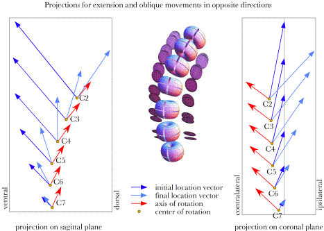
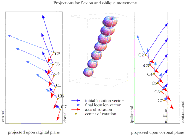
There are three other options for combined sagittal and oblique movements. These will be introduced more briefly in the following figures. The situation just considered had the sagittal and oblique movements in the same direction in that both were negative excursions. It really does not make sense to think of them as being either in the same direction or opposite directions in as much as they are orthogonal rotations, just as it makes no sense to say that right lateral rotation is in the same direction as right side flexion, but it is commonly done. Let us say that in the situation just considered both rotations had the same sign. The combination of flexion and left oblique rotation would also have the same sign. The other two options will have opposite signs. Next, let us consider extension with right oblique movements. As the following figure indicates the movements are symmetrical with those for right oblique movements. Whereas the axis of rotation were directed caudally and ventrally in the sagittal plane they are pointed rostrally and dorsally in this instance. When the signs were the same the rotation axes were to the right and caudally in the coronal plane, they are to the right and rostrally when the signs are opposite. The centers of rotation are again on the side opposite the direction of oblique rotation, but in this instance that places then symmetrically on the right side rather than the left side.
Projections of the axes and centers of rotation for an artificial lower cervical spine that is rotated into extension and left oblique rotation.
When the movements are flexion and left oblique rotations, then the signs of the rotations are the same, both positive. The axes of rotation are in the opposite direction from those when both movements are negative. In fact, when viewed directly from the side, the axes of rotation for the rotation with both components of the same sign line up to form double headed arrows that point in opposite directions. The two situations where the signs are opposite also have opposite rotation axes. Centers of rotation for flexion are located ipsilateral to the direction of rotation and they become further lateral with progression to more rostral vertebrae. For extension, the centers of rotation are contralateral to the direction of rotation. The tools that were developed to describe concatenated movements have been applied to all of these configurations and we have noted some symmetries in the axes of rotation and centers of rotation of the various movements to eccentric configurations from neutral gaze. In the next section, these symmetries will be explored in greater depth.
Projections of the axes and centers of rotation for an artificial lower cervical spine that is rotated into flexion and left oblique rotation.
Projections of the axes and centers of rotation for an artificial lower cervical spine that is rotated into flexion and right oblique rotation.
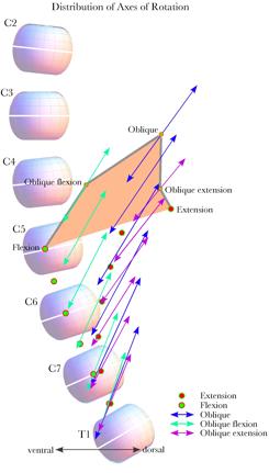
Distribution of the axes of rotation for necks moving to eccentric configurations from neutral configurationIt is possible to pull all of these plots together into a single plot that illustrates the distributions of the axes of rotation and centers of rotation for all the movements considered in the last section. The next couple figures attempt to realize that goal in two projections. The first is the projections of the axes of rotation upon a sagittal plane. For comparison, the lower cervical spine in neutral configuration has been plotted to the same scale and location.
The distribution of the axes of rotation has been plotted for movements away from neutral configuration to a collection of equally spaced eccentric configurations. The points at the apices of the orange area are the centers of rotation for the C2 vertebra. The gray margins of that area connect adjacent configurations as the lower cervical spine moves in a circle. The centers of rotation for the C7 vertebra moving upon a stationary T1 vertebra lie in a compact group between the vertebrae. Indeed, the axes of rotation for each vertebra moving upon the subjacent vertebra are as compact. However, as one progresses rostrally the concatenated actions for the subsequent vertebrae cause the equivalent movements to spread. The apices of the orange polygon indicate the centers for C2. Since the axes of rotation for flexion and extension alone are perpendicular to the sagittal plane, they are indicated by circles in the figure. If we consider the lower cervical spine to swing from full extension to full oblique to full flexion, then the centers for rotation from neutral configuration to each successive eccentric configuration are connected by the gray lines along the upper edges of the polygon. The axes are not the axes of rotation that carry the neck between the successive configurations. Those centers and axes of rotation are considered below and they are quite different from these.
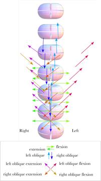
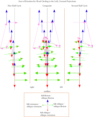
The centers of rotation and axes of rotation for the movements from neutral configuration to a collection of eccentric configuration are plotted as projections upon a coronal plane. The lower cervical spine in neutral configuration is drawn to the same scale and location for comparison. There is a pronounced right/left asymmetry in the axes of rotation. All the centers of rotation are shifted caudally relative to the moving vertebra and most are dorsal to the vertebral bodies. Many of the oblique centers of rotation would lie within the lower cervical spine. The centers of rotation for the C2 vertebra are the exception in that all the more dorsal centers lie dorsal to the vertebral spine. Another viewpoint on this data may be obtained by projecting the centers of rotation and the axes of rotation upon a coronal plane. That has been done in the above figure. There is an asymmetry between the two sides in the directions of the axes of rotation that is not as obvious when the axes are plotted on a sagittal plane. That is because the corresponding movements on the two sides have axes of rotation that are in exactly opposite directions and start at the dame points in the projection plane when projected. In this view, we can see that a substantial distance in the medial/lateral direction separates the two vectors. As we progress to more rostral vertebrae, the centers of rotation spread laterally, except for pure flexion and extension. Axes of rotation when the neck moves between eccentric configurationsAll of the axes of rotation considered so far are for movements from neutral configuration to eccentric configurations. Let us now consider how the axes differ when moving between eccentric configurations. The example that will be considered is the situation when the head is in full extension and it rotates to the right into full right oblique and then into full flexion and back into full extension by way of full left oblique. The axes of rotation for each joint, at each stage of the rotation, are computed and they are plotted in the following figures. These types of plots are difficult to appreciate in projections such as those shown here. The calculations in Mathematica The next figure shows the axes as viewed from straight in front of the lower cervical spine. The figure shows the axes for the first half cycle in the left panel and the second half cycle in the right panel, with the two superimposed in the middle panel. When the two half cycles are superimposed, it becomes evident that the axes are asymmetrically distributed. The differences are subtle for the more caudal vertebrae, but pronounced for the most rostral vertebrae. The pink arrows indicate the sequence of axes of rotation for the C2 vertebra as the neck circles. The primary asymmetry is in the placement of the centers of rotation relative to the midline. Many of the pairs are shifted to the right side. There is also a reversal of the most rostral axes for oblique movements to and from flexion and full oblique configurations on the right side. That reversal does not occur on the left. .
The axes of rotation for movements between eight equally spaced configurations during circling the neck from full extension to the right through full oblique to full flexion and then through full left oblique and back to full extension. The left panels contains the axes for the first half of the cycle and the right panel shows the axes for the second half cycle. In the middle panel they have been superimposed. The axes have been color coded to indicate the phase of the cycle for which they occur.
The axes of rotation for the circling movements in the last figure have been plotted to show their distribution when projected into the midsagittal plane. For comparison, the lower cervical spine in neutral configuration, fully flexed, and fully extended configurations are also plotted. The color-coding is the same as in the previous figure. The distribution of the axes of rotation for the circling movements are plotted from the lateral perspective in the above figure. Because most of the movements between full oblique and the flexed and extended oblique configurations are nearly perpendicular to the midsagittal plane, they appear markedly foreshortened. Movements to and from full extension (red arrows) and full flexion (blue arrows) are much more widely distributed than those to and from full oblique configurations (green arrows). All the axes of rotation are plotted relative to a lower cervical spine in neutral, fully flexed, and fully extended configurations. It should be noted that the axes for rotations to and from full extension and full flexion are relative to spines that are quite different from neutral configuration. Still the centers of rotation are more rostrally placed than those for movements to and from full oblique configuration. Axes and centers of rotation as a function of the magnitude of a movement
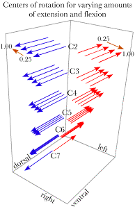
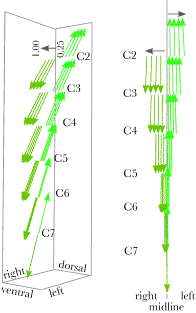
Axes of rotation for a series of increasingly greater sagittal movements in the same direction. As a movement increases in its magnitude, the center of rotation shifts and there is often a small change in the direction of the axis of rotation. In the following, we will consider a few instances of movements that vary in size. The calculation uses 25%, 50%, 75%, and full (100%) extension and flexion and the same gradations of oblique movement in each direction. For the sagittal movements, the axes of rotation move in opposite directions. All the axes of rotation are perpendicular to the midsagittal plane, which contains all the centers of rotation. The centers for flexion lie ventral and a bit caudal to the centers of rotation for extension. As the excursion of the movement increases, the centers of rotation for extension shift dorsally and those for flexion shift ventrally. Similarly, for oblique movements the centers of rotation shift laterally as the movement excursions become larger. In addition, there is a small change in the directions of the axes of rotation with larger movements. In general, small movements have centers of rotation that lie close to a curvilinear axis in the midsagittal plane and larger excursions shift the centers of rotation away from that axis. The effect is greater for more rostral vertebrae or vertebrae further from the point of reference.
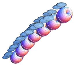
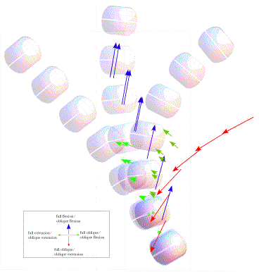
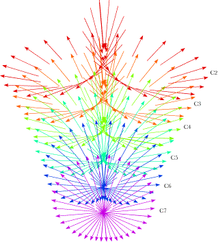
Rotation vectors for a series of increasingly large oblique movements in the same direction. Axes of rotation and centers of rotation for finely divided movementsAs we subdivide a smooth curvilinear movement into many parts, the axes of rotation for the individual components of the movement form a series of gradually changing vectors that move in space as they change in direction. In the limit, as the segments of the movement become shorter and shorter, the series of vector axes sweep out a sheet that forms a mathematical object similar to a derivative of the movement. The vectors are the vector components of the quaternions that are the ratios of successive orientations. The direction of each vector is the axis of rotation, and its location is the center of rotation. Those attributes vary according to the momentary placement of the vertebra and the rate and direction of the change in that placement. The translation component was not considered here, because, as the difference between successive placements shrinks, the translation component becomes very small. In the limit, it goes to zero. Such calculations lead to trajectories of rotation quaternions, which are more complex than the equivalent movements that this chapter started with, but, in the limit, they lead to a characterization of the movement without a translation component. Although the term is not precisely correct, these vectors may be called instantaneous axes of rotation The following calculations, fractionating a movement into many small segments and calculating the center of rotation and axis of rotation for each segment, lead us to a new concept. The trajectories of axes of rotation and centers of rotation are conceptually similar to evolutes of planar curves. However, the sets of centers and axes of rotation of the placements of the cervical vertebrae as the lower neck passes through its movement are substantially more complex. An evolute of a curve is the curve composed of the centers of curvature for the points along the curve (Gray 1998; Weisstein 2003, also see the next chapter). For each point on the original curve, called the involute, one finds the point on a line perpendicular to the curve that is the center of the circle coincident with the curve at that point. As one moves along the involute, the centers of curvature trace out another line, which is the evolute. Similarly, as a bone moves through space, it usually changes both location and orientation, that is, its placement. The protocol that will be used to calculate the centers of rotation and axes of rotation for small segments of the movement generates a more complex mathematical entity than the curve that is an evolute, but it is conceptually rather like an evolute. Since the term ‘evolute’ is derived from the past participle of the Latin verb ‘evolvere’, meaning to roll out, let us use the actual past participle ‘evolutus’ to describe the trajectories of centers and axes of rotation for movements of an orientable object. An evolutus is a ‘rolling out’ of the movement. To illustrate the concepts of instantaneous axes of rotation and evoluti, consider a rotation of the lower cervical spine that passes successively through the extreme configurations for full right oblique to full extension, full left oblique, full flexion and back to full right oblique. The configurations were computed by multiplying the sagittal rotation in each joint by the sine of elapsed time and the oblique rotation by the cosine. The circling movement was sampled at 10° intervals and the ratio of successive placements calculated for each vertebra. All of the rotational components of the ratio are plotted in the following figure. Each vertebra’s evolutus of instantaneous axes of rotation is plotted in a different color to make their distribution more readily apparent. It is difficult to obtain an accurate impression of the array of vectors from such projections into a plane, but one can get some idea of the sheets of unit vectors generated by the movement. Viewed in three dimensions, the array of evoluti is rather like a rotifer head that rises to a peak ventrally. It should be noted that these evoluti are for movement in one direction around the circle. If the neck moves in the opposite direction, the centers of rotation would be much the same, but the unit vector would point in the opposite direction. The evolutus would appear rather different, but it would be mathematically very similar.
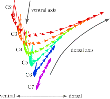
Instantaneous axes of rotation for the lower cervical vertebrae during a circular rotation of the neck from full right oblique through full extension, full left oblique, full flexion and back to full right side oblique. Each vector indicates the center of rotation and the axis of rotation for 10° of rotation and each color indicates the rotation axes for a different vertebra. The vectors for the C7 vertebra (purple) form a disc that is close to a tilted plane. Closer attention reveals that the centers of rotation lie on a curve that spirals between two planes. Ventrally the centers for flexion approach a more vertically tilted axis (ventral axis in the following figure) and they are generally contralateral to the direction of the tilt of the vertebra. For more rostral vertebrae, the ventral centers take longer to become contralateral to the moving vertebra, but the inclination of that cusp of the curve tends to be similar for all vertebrae. The movements in the extension part of the cycle have centers that lie ipsilateral to the moving vertebra and they lie in a less tilted plane (dorsal axis in the following figure).
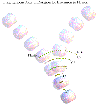
The instantaneous axes of rotation for a circling movement are plotted from a lateral viewpoint. It is apparent that the sheet of vectors has a ventral prow that approximates the indicated ventral axis and a dorsal shelf that approximates the dorsal axis. The part of the evolutus at the ventral limit is similar for all the vertebrae, but the parts near the dorsal limit become more horizontal for progressively more rostral vertebrae. Let us now return to the basic joint movements about the transverse and oblique axes. If we divide the excursion from full extension to full flexion into a series of small movement segments and compute the effective movements for each segment, then the distribution of centers of rotation and axes of rotation is as illustrated in the following figure. The movement has been broken into 20 equal steps and the center of rotations for the segments are plotted for each vertebra. The centers are plotted against the lower cervical spine in full extension and full flexion. The axes of rotation all project directly out of the midsagittal plane, perpendicular unit vectors directed to the left of the plane. Clearly, the centers of rotation are approximately evenly distributed along a curvilinear trajectory extending from behind the spine in full extension to a short distance ventral to the mid-coronal plane of the vertebrae in full flexion. The more rostral the vertebra the longer the trajectory and the length of the trajectory increases more rapidly then the distance between trajectories, so that the ventral and dorsal extremities of the trajectories form curves that are concave dorsally and ventrally. The centers are ordered so that the most dorsal segments of the movement are about the most dorsal centers of rotation and the most ventral segments of the movement about the most ventral centers. The centers of rotation are displaced a substantial distance caudally from the moving vertebra, so that, the center of rotation for the C2 vertebra are at the level of the C5 vertebral body.
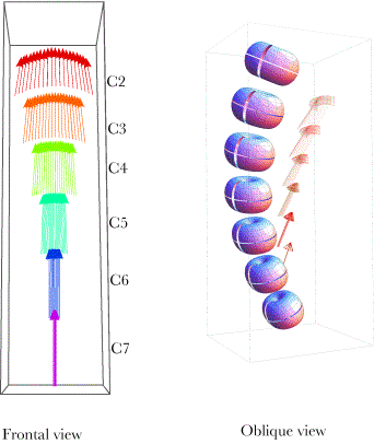
The centers of rotation for each lower cervical vertebra are plotted for a finely fractionated movement (20 equal steps) from full extension to full flexion. The centers are plotted against the lower cervical spine in both full flexion and full extension. When a movement is broken into a series of fine segments, the movements are almost entirely swing. The translation component goes to zero as movement segment length becomes less. That is generally true of the fractionation of movements. Consequently, in the limit, fractionating a smooth movement causes the equivalent movement to be a series of swings about axes of rotation that have their centers of rotation along a smooth trajectory. We can carry out the same type of analysis for oblique movements of the lower cervical spine. The following figure illustrates the centers and axes of rotation for a finely divided oblique excursion from full right oblique to full left oblique.
The axes of rotation are plotted for oblique movement from full right oblique configuration to left full oblique configuration. In the left panel, the vectors are viewed from the ventral aspect and in the right panel the axes are plotted relative to the spine in full left oblique configuration. When viewed from the front (left panel) the axes of rotation for each vertebra form a curved sheet that is concave dorsally. As with the extension/flexion axes, the fractions of the movements that are to the left move about and center of rotation to the left of the midline and those for movements on the right side have their axes of rotation on the right side. The centers of rotation are generally caudal to the moving vertebra, but not as far caudal as for extension and flexion. The centers for C2 are about level with the caudal part of the C4 vertebra. The centers for more rostral vertebrae are more dorsal than those for the more caudal vertebrae. SummaryIn conclusion, we have progressed from the calculation of the equivalent movements for simple movements from neutral configuration to full extension, full flexion, full oblique, and combinations of sagittal and oblique movements. Such movements have a rotation component and a translation component, but the translation component becomes substantial only for the more rostral vertebrae. We then considered movements between adjacent eccentric configurations, which are quite different from those from neutral gaze. The rotation quaternions occur in a series of rather differently directed and located directions. There is a sense of an ordered series of rotation vectors, but the pattern is not obvious. Those calculations of a series of connected steps of movement led to the concept of fractionating a movement into many small segments and calculating the center of rotation and axis of rotation for each segment. Such calculations lead to trajectories of rotation quaternions, which are more complex than equivalent movements, but, in the limit, they lead to a description without translation components. Such collections of localized rotation quaternions are called evoluti and their elements are called instantaneous axes of rotation. Gray, A. (1998). Modern Differential Geometry of Curves and Surfaces with Mathematica. Second Edition. Boston, CRC Press. Kapandji, I. A. (1974). The Physiology of the Joints. Annotated diagrams of the mechanics of the human joints. New York, Churchill Livingstone. Weisstein, E. W. (2003). CRC Concise Encyclopedia of Mathematics. Second Edition. Boca Raton, Fl., CRC Press. | ||||||||||||||||||||||||||||||||||||||||||||||||||||||||||||||||||||||||||||||||||||||||||||||||||||||||||||||||||||||||||||||||||||||||||||||||||||||||||||||||||||||||||||||||||||||||||||||||||||||||||||||||||||||||||||||||||||||||||||||||||||||||||||||||||||||||||||||||||||||||||||||||||||||||||||||||||||