Annotated Table of Contents
Preface
The principal concepts to be considered in reference to
quaternions and anatomical movements are discussed briefly. The preface is an argument for the
approach that will be followed in this book. Anatomical movements
are movements of a body or a portion of a body. In particular, we will concentrate upon rotations of
anatomical objects.
It is argued that both location and orientation are central
to understanding anatomical movements.
The orientation component is usually forgotten or implicitly assumed
without formal acknowledgement.
The location, extension, and orientation of an anatomical
object can be expressed by arrays of vectors, called framed vectors, that are
transformed by quaternion multiplication in the same manner as the represented
anatomical objects are transformed by rotations in three-dimensional space. The use of quaternions to express
rotations in three-dimensional space is an intuitive and powerful approach to
the description of anatomical movements.
[top of page | return to Table of Contents]
Introduction
to Quaternions and Anatomical Movements
The fundamental concepts upon which this book is based are
defined and related to the problem of describing anatomical movements.
Quaternions are
defined as the ratios of vectors.
That is their most useful interpretation for present purposes.
Orientation is
expressed as an ordered set of three mutually orthogonal unit vectors, called
frames of reference. The difference between right-handed and left-handed frames
of reference is described and the convention of using right-handed systems
introduced.
The concepts of location, extension, and orientation are
examined and the possibility of their expression by vectors is introduced. The full set of descriptive vectors,
which encodes location, extension, and orientation, is called a framed
vector. A framed vector is a set of vectors that stand as a formal
equivalent for the anatomical object under consideration.
The combination of location and orientation that define an
anatomical object are called its placement. Anatomical description is the
expression of placement together with a description of its extension. All of these attributes are encoded in
framed vectors.
The concept of representing rotations of anatomical objects
by conical rotations of vectors is briefly introduced. A conical rotation is rotation that occurs about an axis of rotation
that is not orthogonal to the rotating vector.
[top of page | return to Table of Contents]
An
Intuitive Logical Formalism for the Description of Anatomical Movements
In order to describe anatomical movements it is necessary to
develop a number of concepts related to the formal structure of quaternions and
their algebra, how they are formally equivalent to rotations of vectors in a
plane, and how they may be used to represent conical rotations.
Spin and swing are introduced and it is argued that they can
be defined only relative to the orientation of an object. Informally, spin a rotation about the anatomical axis of an object
and swing is any other rotation
of the object. If the anatomical
axis of the rotating object is perpendicular to the axis of rotation, then the
swing is a pure swing.
A number of examples of the calculation of anatomical
movements about axes of rotation are considered, to illustrate the basic
approach and its consequences.
[top of page | return to Table of Contents]
Transformation
of Orientation: Revisiting Spin and Swing
The concept of null spin is introduced. Null spin occurs is when two orientations may be transformed into each other by
a single rotation confined to a single plane. The concept depends upon the concept of a ratio of
orientations. A ratio of
orientations is the quaternion that rotates
the first orientation into the second orientation.
A method for computing the ratio of two orientations is
introduced and demonstrated. The method for computing the ratio of two
orientations involves finding two planar rotations that can be concatenated to
obtain the conical rotation that is the ratio. An illustrative example is considered.
Finally, the use of ratios of orientations to characterize
the anatomy of a bony assemblage and to compute the consequences of movements
in such an assemblage is illustrated by describing the arm/forearm linkages in
terms of framed vectors and computing a two-part movement in that assemblage.
[top of page | return to Table of Contents]
Examination
of Transformations of Orientation in a Universal Joint
The eyeball in its orbit is a straightforward system for
exploring the nature of movements in a universal joint controlled by six
muscles with a clearly defined performance objective. Because the eye sees best when the visual image is correctly
oriented upon its retina, we have a well-defined criterion for
performance. It is shown that that
constraint on movement leads to two well established basic relationships for
eye movements, Listing’s Law and Donder’s Law.
Donder’s Law basically states that for each direction that
the eye looks, there is an optimal orientation of the eyeball, the one that
keeps the visual field meridians aligned as closely as possible with the
retinal meridians. Listings Law
says that for rotations to and from a particular gaze, the axes of rotation of
the eye all lay in a single plane.
We show that Listing’s Law is a logical consequence of Donder’s
Law.
Both laws are very efficiently stated in terms of gaze
direction (location) and gaze orientation. It is impossible to express them without at least implicit
consideration of orientation. The
orientations that satisfy Donder’s Law are the orientations that have null spin
relative to neutral gaze.
Listing’s Law may be framed as a statement about the ratios of
orientation. The rotations that
satisfy Listing’s Law are generally not the shortest trajectory between the two
gaze directions. The shortest
trajectory between two gaze directions, the great circle trajectory, will
generally result in the eye being rotated relative to its optimal
orientation. The trajectory that
will insure that the eye lands with the correct gaze direction and gaze
orientation is the ratio of the null spin orientations for each gaze direction.
Donder’s Law implies a particular set of muscle lengths for
the six extraocular muscles for each gaze direction. The surface generated when we plot the set of muscle lengths
versus gaze direction is computed and illustrated. The surface is complex with
moderate curvature in all the component surfaces.
We also explore the differences in the muscle length versus
gaze direction surface if we assume the presence of a fascial membrane
supporting the eyeball in the orbit and guiding the eye muscles, which is the
actual anatomical situation, versus the usual configuration that is illustrated
in textbooks and atlases, where the membrane is not present. The model with fascial slings for the
external eye muscles changes the surface and flattens the component surfaces to
a modest degree.
The same model allows us to examine the pulling directions
of the individual eye muscles when the eye is looking eccentrically. We are able to consider the degree of
spin and swing generated by each muscle at each gaze direction. In this case, the pertinent anatomical
axis for defining spin and swing is clear from the functional demands of the
eye. There is a simple relationship between swing and spin for a rotating eye.
Finally, we explore a possible mechanism that will ensure
that the eye will always be correctly oriented for each gaze when the eye makes
saccadic eye movements. The
trajectory that will ensure that the eye is correctly oriented is a conical
rotation about the axis of rotation that is the intersection of the Listing’s
planes for the beginning and the ending gazes. It is the ratio of the two planes. The physiological realization of that action is consistent
with the eye muscle lengths during the trajectory lying in the muscle length
surface that was computed on the assumption of Donder’s Law.
[top of page | return to Table of Contents]
Spinal
Dynamics I: The Axio-atlanto-occipital Assemblage
In the next few chapters, we explore a number of topics
related to the anatomy and movements of the cervical spine. In this chapter, the anatomy of the
joints between the occiput of the skull, the atlas vertebra (C1), and the axis
vertebra (C2) are expressed in a model with framed vectors for each bone and
quaternions for each joint motion.
Using the model, it is possible to address a number of questions related
to the anatomy and physiology of that region.
It is determined through calculation from the anatomical
description that the vertebral artery is disposed so that there should not be a
significant strain upon the artery within the skull. On the other hand, there is a definite possibility for
pathological strain in the artery as it passes between the transverse foraminae
of the atlas and the axis. We are
able to calculate the relationship between the excursion into lateral rotation
between the bones and the length of the vertebral artery needed to span the
gap. The changes in the gap
between the foraminae is such that the vertebral artery could not stretch
enough to accommodate the necessary change in length, which explains why there
is a substantial slack in that segment of the arteries. It also indicates why mechanical damage
to the vertebral artery is far more common in that segment than in any other
part of the artery. Should the
amount of lateral rotation in that joint increase even moderately, it is probable
that the vertebral artery would be strained enough to tear it.
The main restraint upon lateral rotation in the
atlanto-axial joint is thought to be the alar ligament, which links the occiput
and the odontoid process of the axis.
It is possible to calculate the consequences of that ligament for movements
between the three bones. Our
calculations, based upon a reasonable anatomical description of the region,
indicate that a small sideflexion of the occiput upon the atlas before lateral
rotation will effectively remove the restraint of the alar ligament upon
contralaterally directed lateral rotation between the atlas and the axis. Doing so will allow significantly
greater angular excursions between the bones and may produce a serious strain
in the vertebral artery as it bridges the gap between the bones. That is clinically relevant because it
is common practice to sideflex the head prior to manipulating the atlanto-axial
joint into endrange lateral rotation.
[top of page | return to Table of Contents]
Spinal
Dynamics II: Lower Cervical Spine Anatomy
The lower cervical spine, including all the joints between
the second cervical vertebra and the first thoracic vertebra, forms a complex
bony assemblage with seven similar elements that move in consistent ways upon
each other. In this chapter, the
anatomy of the lower cervical spine is considered in some detail and a model is
introduced that captures most of the features of the lower cervical vertebrae
that are relevant to its movements.
The lower cervical vertebrae are similar enough in these respects that
it is reasonable to use the same mathematical representation for each
vertebra. A framed vector
represents each vertebra and the movements between pairs of vertebrae are
represented by quaternions and centers of rotation. The movements between lower cervical vertebrae are of two
types, sagittal movements into flexion and extension and oblique movements that
combine lateral rotation and side flexion. Vertebral bodies are graphically represented by flattened
tori and the facet joints by discs.
With the model it is possible to compute the configuration of the lower
cervical spine with any combinations of sagittal and oblique movements in its
joints. A few examples are
illustrated.
[top of page | return to Table of Contents]
Spinal
Dynamics III: Computing Compound Movements
Compound movements,
that is, movements in which there is a combination of rotations and
translations, are considered in this chapter. The movements of the lower cervical spine are complex
functions of the movements in the individual joints. Whereas, the movements between the pairs of individual
vertebrae are essentially rocking movements, the movements of the entire
assemblage of bones may sweep out wide excursions, leaving the more rostral
vertebrae substantial distances from their locations in neutral configuration
and tilted at large angles to their original orientations.
A means of computing the effective centers of rotation for vertebrae and the translations that they
experience is developed in preparation of examining the movements of the lower
cervical spine in some detail. The
effective center of rotation for a movement is contingent upon the point of
reference. It is the location of
the center of a conical rotation on the assumption that the change in
orientation is entirely due to a single conical rotation, starting at the
original location of the anatomical object. Frequently, the actual final location is not the same as
that which would occur because of the computed conical rotation, therefore
there is a concurrent translation. Such a combination of a conical rotation and
a translation that achieves the same movement as a multi-jointed assemblage is
called a compound movement.
[top of page | return to Table of Contents]
Spinal
Dynamics IV: Applying the Model to the Lower Cervical Spine
This chapter describes the application of the model
developed in the last two chapters to the analysis of movement in the lower
cervical spine. The principal
analytic tool is the resolution of the movements of individual vertebrae into
compound movements, a combined rotation and translation. Most of the effort goes into the
determination of the effective centers of rotation for the vertebrae. Several types of movements are
considered.
The first movements considered are from neutral
configuration to endrange flexion, extension, and oblique movements, then
combinations of those movements.
It is observed that the effective centers of rotations for movements of
the more rostral vertebrae are located a substantial distance caudal to the
vertebra. The amounts of caudal
shift of the effective centers of rotation are greater for sagittal movements
than for oblique movements.
Oblique movements also have their effective centers of rotation shifted
out of the midsagittal plane, ipsilaterally or contralaterally, depending on
the particular combination of movements.
Secondly, movements between eccentric configurations are
considered in the same manner.
Initially, the movements are between the primary endrange configurations
in circumduction, then between successive stages of a single trajectory from
neutral configuration.
Finally, the circumduction movement is divided into a series of small segments and the effective centers of rotation, axes of rotation, and translations for each segment are computed. Such finely divided movements resolve into a surface in three dimensions swept out by the centers and axes of rotation. That surface is in some ways like the derivative of the movement and in some ways like an evolute of a curve in three-dimensional space.
[top of page | return to Table of Contents]
Spinal
Dynamics V: Another Oblique Rotation
This brief chapter considers another possible rotation that
is consistent with the anatomy of the lower cervical spine, but not commonly
described in the kinesiological literature although it is easy to perform. The intent is to show how the model
allows one to explore questions that are difficult or impossible to consider in
vivo.
The model shows how movements about the alternate oblique axis of
rotation might appear for the neck in toto and where the movements might be limited by impingements and strains
in ligaments. It also gives a
graphic demonstration of the consequences of shifting the axis of rotation
relative to the orientation of the anatomical object. Rotation about a posteriorly tilted oblique axis of rotation
leads to sideflexion and lateral rotation in the same direction while rotation
about the anteriorly tilted oblique axis of rotation leads to sideflexion and
lateral rotation in opposite directions, as conventionally defined.
[top of page | return to Table of Contents]
On
Evolutes and Frames of Curves
[ Word | PDF | HTML]
When considering the movements of finely divided
trajectories in the lower cervical spine a mathematical object was generated
that was in some ways like the evolute
of a curve in that it traced the centers of rotation for the curve. The evolute of a curve is the
trajectory of the instantaneous centers of curvature for a curve in
two-dimensions. In this chapter,
we consider the calculation of the trajectory of the centers of curvature of a
curve in three-dimensions, a line that has been called an evolutus. In the
process, it is necessary to attach a frame to the curve at each point, so, the
curve has a natural orientation, with its orientation being a consequence of
its curvature. A couple examples
are computed to illustrate the concepts.
[top of page | return to Table of Contents]
Distorting
the Box: Strain in Anatomical Media
This chapter and the next two chapters address the situation
when a frame is distorted by strains in the material where it resides. Unlike the frames considered up to this
point, the frames under consideration are extension frames. Because such frames have a definite
location and the lengths and directions of the axes relative to each other can
change, they are given a different name, being called boxes. In this chapter, the concept of a
box is defined and examined in situations where the matrix that contains the
box is stretched or compressed in one or more directions and when the matrix is
sheared.
A box is a set of mutually orthogonal unit vectors at a
point in a block of material that is strained. The three vectors of the box frame are called its edge
vectors. They can be visualized as the
corner of a small cube of the material.
The strain causes the component edge vectors, ![]() , to be lengthened, shortened, and/or rotated as the material
is stretched compressed, and/or sheared.
It is noted that the scalar of the triple vector product of the box’s
edge-vectors,
, to be lengthened, shortened, and/or rotated as the material
is stretched compressed, and/or sheared.
It is noted that the scalar of the triple vector product of the box’s
edge-vectors, ![]() , the strain quaternion, is equal to the volume of the box,
, the strain quaternion, is equal to the volume of the box, ![]() . That index is
called the volumetric strain. The vector of the quaternion product,
the vector strain,
. That index is
called the volumetric strain. The vector of the quaternion product,
the vector strain, ![]() , is a function of the movements of the box’s edge-vectors
relative to each other. If the edge-vectors remain mutually orthogonal, then
the vector of the strain quaternion is null.
, is a function of the movements of the box’s edge-vectors
relative to each other. If the edge-vectors remain mutually orthogonal, then
the vector of the strain quaternion is null.
The concept of a strain transform is developed as a means of
computing the distortion that occurs when a test box is acted upon by a
strain. The strain transform is an expression of the strain in terms of a
particular set of mutually perpendicular axes. A strain transform acts upon a test box to generate the
strained box.
It is shown
that the distortion of the box by strain depends upon the orientation of the
unstrained box relative to the strain.
If the strain is only expansion and/or compression, then it is possible
to find a box that experiences only volume strain. If the strain shears the matrix, then there is no box that
will not experience vector strain.
On the other hand, most boxes experiencing only expansion and/or
compression will experience vector strain, unless their edge vectors are
aligned with the directions of expansion and/or compression. It turns out to be very difficult to
determine if a strain involves shear or not based on the distortions it causes.
[top of page | return to Table of Contents]
Bubble
Strain: The Measurement of Shear by the Distortion of Spheres
Boxes are point functions in the sense that they are defined
at points in the strained matrix.
In this chapter, we explore a different way of looking at strain. Instead of three orthogonal vectors at
a point we assume a sphere of material and look at how it is distorted by
compression and/or expansion versus shear. With this approach it is possible to
effectively examine all possible test boxes at the same time and one can see
that there are definite geometrical principles that determine the nature of a
test box, contingent upon its orientation.
Initially, a means is described for sampling a sphere
uniformly, so that one can obtain reliable statistics for the distortion. It involves computing the vertices of a
dodecahedron and/or an icosahedron inscribed a unit sphere. The vectors to the vertices are
strained according to the strain transform derived in the last chapter and the
array of distorted vertices sketches a distorted surface that depends upon the
nature of the strain.
It is found that while the details of the distortion are
different in the two situations, the result is similar. The distorted sphere becomes an
ellipsoid, called the strain ellipsoid.
With compression and/or expansion the ellipsoid may be prolate or oblate. The axes of the ellipsoid are in the
directions of the compressions and/or expansions. With shear, the distorted
sphere is a prolate ellipsoid.
Shear creates an ellipsoid that is tilted relative to the shear
direction. One can determine the
shear direction from the tilt of the resulting prolate ellipsoid.
Because all shear ellipsoids are prolate and some
combinations of compression and/or expansion produce prolate ellipsoids, any
shear ellipsoid is equivalent to the ellipsoid for a particular combination of
compressions and/or expansions.
However, the two strains are not equivalent, because the compressive
strain that matches the shear strain must continually change direction as the
shear angle changes even though the direction of the shear is constant.
The relationship between the amount and direction of shear
and the distortions of the sphere is derived and plotted. A method of finding the plane of the
shear, given a shear ellipsoid, is developed and illustrated.
[top of page | return to Table of Contents]
Orthogonalized
Strained Boxes
In this chapter, we return to a consideration of strained
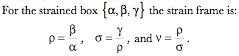
boxes and define a new concept, the strain frame. The strain frame of a
distorted box is a frame of mutually orthogonal vectors that is derived from
the relationships between the axes of the strained box. The unit vector of the ratio of the
second axis to the first is ![]() , the ratio of the third axis to
, the ratio of the third axis to ![]() is
is ![]() , and the ratio of
, and the ratio of ![]() to
to ![]() is
is ![]() .
.
The strain frame provides an orientation for a strained box, which would otherwise lack a definite orientation. It is argued that the strain frame for an unstrained box is indefinite until the box is strained, at which time it takes a definite value, contingent on the nature of the strain. So, although an unstrained box has a clear orientation, aligned with its axes, its strain frame is undefined until the strain is specified. Consequently, the strain frame is not identical with orientation. This a desirable property of strain frames when computing the ratios of orientations that occur with strain.
It is shown that, as a consequence of the manner in which a
strain frame is defined, the strain quaternion can be expressed a function of
the components of the strain frame. The ![]() and
and ![]() axes of the strain frame are the vectors of the strain
quaternion in special cases, when only pairs of the test box axes are shifted
by the strain. When the strain leaves no two axes mutually perpendicular, then
the strain quaternion is a function of all three strain frame axes. There is an interaction between the two
rotations, which causes the vector of the strain quaternion to extend in the
direction of the
axes of the strain frame are the vectors of the strain
quaternion in special cases, when only pairs of the test box axes are shifted
by the strain. When the strain leaves no two axes mutually perpendicular, then
the strain quaternion is a function of all three strain frame axes. There is an interaction between the two
rotations, which causes the vector of the strain quaternion to extend in the
direction of the ![]() axis. As the distortion is reduced, the
vector of the strain quaternion moves nearer to the plane determined by the
axis. As the distortion is reduced, the
vector of the strain quaternion moves nearer to the plane determined by the ![]() and
and ![]() .
.
One can invert the strain quaternion when it is expressed in
terms of the strain frame to obtain the rotations of the test box axes. When no two edge vectors are mutually
orthogonal, the vector component of the strain quaternion is not obviously
indicative of the internal rotations.
It is necessary to project the strain quaternion vector upon the
component axes of the strain frame for the strained box. However, doing so leads directly to the
desired excursions about the ![]() and
and ![]() axes.
axes.
[top of page | return to Table of Contents]
Distortion
in Media: Compressive and Tensile Strain
In this chapter the nature of compressive and tensile
strains are analyzed with some of the tools developed in the last few
chapters.
Initially the situation in which the medium is not allowed
to spread laterally is analyzed, primarily to establish the basic approach in a
situation where the mathematics is less challenging. It is found that the strain of a framed vector in a medium
that is allowed to contract or expand in one dimension is proportional to the
displacement of the moving face.
The strain quaternion is a scalar and the rotation quaternion for the
orientation frame is unity.
The situation is more difficult where the medium is allowed
to flow in the plane perpendicular to the moving face. Initially we find the amount that the
lateral margin of the medium moves, assuming laminar flow. Using that information, together with
the derivation for the vertical movement of the medium experiencing compressive
or tensile strain, it is possible to determine how any point in the medium
moves. Using that information it
is possible to compute flow lines in the medium and the amount of distortion in
test boxes that experience the strain.
The strain quaternion may be computed from the strained box.
[top of page | return to Table of Contents]
Distortion
in Media: Shear Strain
In this chapter the nature of shear strains is analyzed with
the same tools as in the last chapter.
Two types of shear strain are examined: linear shear and rotational
shear.
With linear shear, the change in location has a
characteristic profile with less strain near the moving surfaces and maximal
strain in the middle of the sheared slab.
That profile leads to no stretching or contraction in a horizontal plane
parallel with the moving surface(s), but a tilting of the vertical axis at an
angle that depends upon the depth in the slab. The degree of tilting is computed and plotted. It is shown that there is no volumetric
strain in the sheared medium.
Orientation does not change in a linearly sheared slab of material.
With uniform rotational strain the situation is similar
except that the shear occurs in concentric rings about the axis of
rotation. Changes in location are
expressed in terms of angular excursions.
The derivations are more complex than those for linear strain, but the
end result is similar. There is no
volumetric strain, but there is vector strain that depends upon depth in the
slab. All of the strain axes are
rotated by the change in location, therefore there is a change in orientation
as the material is sheared.
[top of page | return to Table of Contents]
Quaternion
Numbers
Quaternions are interesting in themselves as a special type
of number. Numbers are explored as
a series of generalizations from counting numbers to integers, real numbers,
imaginary and complex numbers, quaternions and octonions. The algebra of quaternions is
introduced and a number of special quaternions are defined, such as the inverse
and the conjugate of a quaternion.
The interpretation of quaternions as rotations in
three-dimensional space and their use for expressing conical rotations are
reviewed.
The orientability of quaternion vectors is discussed and the
concept of frames of reference as expressions of orientation is
considered.
It is shown that the ratio of two planes is their
intersection.
A protocol to compute the ratio of two orientations is
outlined and illustrated with examples.
The chapter closes with a brief introduction to the
differentiation of quaternions and orientations.
[top of page | return to Table of Contents]
Final
Thoughts on the Control of Placement in Anatomical Systems
The fundamental premise of this book is that placement, a
combination of location and orientation, is a central concept in the
description of anatomical movements.
It must also be central to the control of movement by the nervous
system.
The traditional approach is fundamentally a qualitative
approach, based upon cardinal directions of movement. It is argued that traditional methods of describing
anatomical movements are both inaccurate and inadequate for a careful
description of movement in anatomical systems. Beyond that, it is common practice in the traditional approach
to assume many elementary attributes of the system are obvious when they are
not. In fact, the values of
anatomical axes or axes of rotation may be and often are variables. In the traditional approach one must
often determine their values from context. That is not a fundamental flaw in that it is always possible
to define them explicitly, but it is often not realized that it is necessary to
do so.
Many of the fundamental concepts of anatomical descriptions
of movement are dependent upon the context in which they are viewed. In the traditional approach, that
context is often unstated or implicitly assumed to take a particular
value. In the approach outlined here,
the values of all parameters and variables must be specified. It is fundamentally a mathematical
approach based upon quaternion analysis and the expression of location,
extension, orientation, and axes of rotation by vectors or sets of
vectors. The concepts of frames
and framed vectors are at the foundations of all of the models and discussions
in this book.
The framed vector approach to the description of anatomical
movements starts with an anatomical description. That description is expressed in a manner that allows one to
move smoothly and naturally from the anatomical description to the movements of
the structure, where all movements occur within the constraints of the
anatomy. The language used to
couch the anatomical descriptions is a powerful, intuitive, efficient means of
expressing anatomy in such a way as to lead naturally to computation.
In the first part of this book, frames of reference are
rigid structures that move as a unit.
In the second part, it is demonstrated that allowing an extension frame
or box to be distorted by local strain in a medium provides a useful means of
characterizing strain and computing the resultant flow in the medium. The behavior of boxes provides another
application of the type of approach introduced by this book.